

Digital Logic Circuits And Design

Digital Logic Circuits And Design
MP4 | Video: h264, 1280x720 | Audio: AAC, 44.1 KHz
Language: English (US) | Size: 2.87 GB | Duration: 9h 5m
MP4 | Video: h264, 1280x720 | Audio: AAC, 44.1 KHz
Language: English (US) | Size: 2.87 GB | Duration: 9h 5m
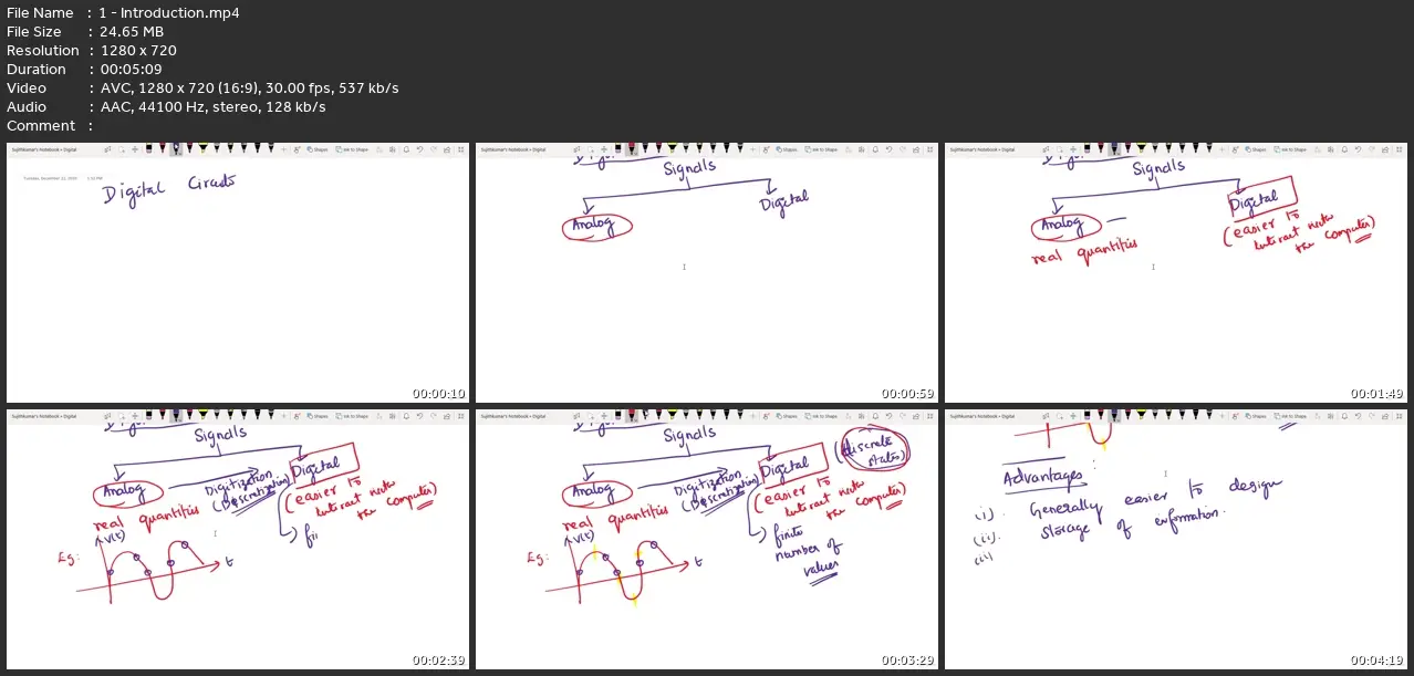
Learn how to design a digital circuit in the simplest way in the world of digital electronics
What you'll learn
Digital Electronics
Digital Circuit Design
Digital Logic Design
Requirements
No, There are no pre requisites.
Description
After completing this course, you'll be able to 1. Understand all the fundamentals of number systems and performing conversion between them. 2. Function of logic circuits and how to design them. 3. Classify Combinational Logic and Sequential Logic. 4. How to design a combinational logic circuit for a given scenario with the minimum number of gates possible.5. Use all the standard techniques to minimize the logic gate requirements6. Design sequential logic circuits like Counters and Shift Registers using Flip flops. 7. Understand the working of various flip flops and latches and highlight the difference between them. If you're an aspirant who belong to the field of Computer Science, Electronics and Information Technology, Then this course will strongly build the foundations of the digital electronics in you. Objective of the course is to make everyone design a digital circuit efficiently using various components.Digital systems contain information that is represented as binary digits called bits.The alphabet of these bits is the set {0, 1}, which represents the logical value of thebits. The physical value is determined by the logic family being used. The transistor-transistorlogic (TTL) family represents a logic 0 typically as + 0.2 volts and a logic 1typically as + 3.4 volts using a + 5 volt power supply; the emitter-coupled logic (ECL)100K family represents a logic 0 typically as – 1.7 volts and a logic 1 typically as –0.95volts using a – 4.5 volt power supply.Thus, a signal can be asserted either positive (plus) or negative (minus), dependingupon the active condition of the signal at that point. The word positive, as usedhere, does not necessarily mean a positive voltage level, but merely the more positiveof two voltage levels, as is the case for ECL.
Who this course is for:
Beginner Electronics, CS and IT Aspirants
Digital Logic Circuits And Design